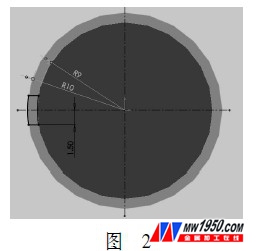
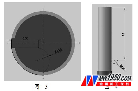
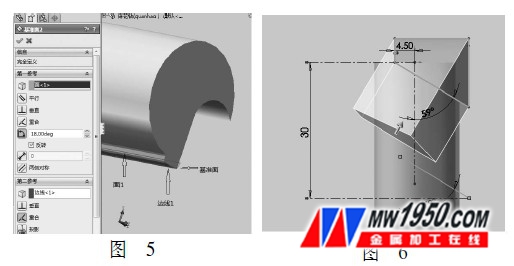
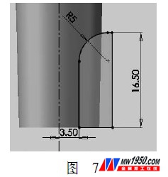
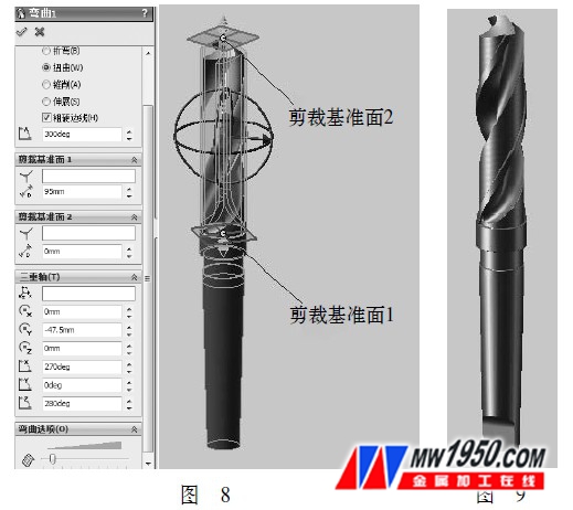
In this paper, the SolidWorks modeling function is used to model the twist bit solid body. The following describes the modeling process for the reader's reference. 1. Create a drawing Open SolidWorks, click the New, Part, and OK icons, and select Front Look Datum as the drawing plane in the file interface feature tree. Click "Sketch" to enter the sketch drawing state, draw the sketch shown in Figure 1 based on the coordinate origin, and exit the sketch after the sketch is drawn. Click the Rotate icon in the feature toolbar to enter the Rotation property manager for parameter options. Click the datum point line in the drawing area sketch as the Rotation Parameter option, select One Direction in Rotation Type, enter 360° in the Angle option, and click the confirmation option “√†to generate the sketch. Draw the sketch shown in Figure 2 by selecting the top reference plane in the feature tree. Click the pull tab/base icon in the feature toolbar to enter the Boss-Stretch property manager for parameter options. Select Sketch Datum and select Form to Next in Direction 1. The default "Merge Results" option "√", and finally click the confirmation option "√" to complete the stretching of the sketch. This completes the establishment of a twisted shank flank entity. Select the top reference plane in the feature tree and draw the sketch shown in Figure 3. Click on the side of the boss 2 (twisted bit flank) of the sketch 2 to draw a sketch, as shown in Figure 4. Click the Cut Scan icon to enter the Cut-Scan property manager for parameter options. The default "contour scan". Click "Sketch 3" and "Sketch 4" in the feature tree as "Path" and "Contour" as the cut scan section, as shown in Figure 5. Finally, click the confirmation option “√†to initially complete the establishment of the twist groove of the twist drill. 2. Base plane establishment Click the “Datum Plane†icon on the toolbar to make the parameter options in the pop-up datum Attribute Manager selection bar. Click on the other side of the boss (twisted knives) of the sketch 2 as the first reference, and select "18°" in the angle check box; click on the straight line of the spiral groove and the minor flank face of the twist drill. For the second reference, click "coincident" in the check box. Finally click on the confirmation option "√" to complete the establishment of the "base" (see Figure 5). Click on the created datum and draw a sketch as shown in Figure 6. Click the "Rotate Cut" icon to enter the "Cut-Rotate" parameter option. Click the lower line in the sketch as the "Rotary Axis", select "80deg" in the rotation angle, and click the upper contour in the sketch to complete the "Selected Outline" option in the check box. Click the confirmation option “√†to complete the cutting of the half twist drill by “cutting the rotationâ€. Select the front reference plane in the feature tree to draw the sketch shown in Figure 7. Click the Extrude Cut icon to enter the Cut-Extrude parameter option. Select “Sketch Datumâ€, select “Full Through†in “Orientation 1†and “Orientation 2â€, and click the confirmation option “√†to complete the cut and stretch of the sketch, thus completing the partial shape creation of the flat tail. 3. Modeling Click the "Insert" and "Circumferential Array" icons to enter the "Circumferential Array" parameter option. In the Array Axis option, click the datum in the drawing area to stretch the solid axis, enter 360° in the Angle option, 2 in Instances, and click the Equal Spacing option √. Click the "Features to Array" checkbox to select the "Stretch", "Remove Scan", "Cut Out Rotation", "Cut Stretch" commands in the feature tree. Click the confirmation option “√†to complete the creation of the other half of the flank, straight groove and flat tail. Click the Bend icon to enter the Bend feature parameter option, select the Bend type as Twist in the Attribute Manager, select the Array feature as the distort object in the drawing area, and the twist axis and the two crop datums appear. Enter 360° in the attribute manager twist angle input box, enter 95mm in the crop reference plane 1 input box, input 0mm in the crop reference plane 2 input box, and input the rotation origin x, y, z in the triad input box. 0mm, -105mm, 0mm, input rotation angle 270°, 0°, 150°, click the confirmation option “√†to complete the bending feature shape, as shown in Figure 8. Finally, click the “rounded corner†icon, select “equal radius†in the attribute manager “rounding typeâ€, enter 0.2 in the rounded item, and click the sharp corner of the drill in the entity in the drawing area. Click the confirmation option "√". Complete the rounded corners of the twisted corner of the twist drill (see Figure 8). At this point, the twist drill model is finished, and finally we select “Editâ€, “Appearance†and “Color†in the main menu to make it more realistic (see Figure 9). Cermet Inserts,Milling Cermet Inserts,Cnc Milling Cermet Inserts,Inserts Milling Cutting Tools Zhuzhou Zhirong Advanced Material Co., Ltd , https://www.zrcarbide.com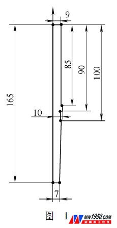
SolidWorks2010 making twist drill model