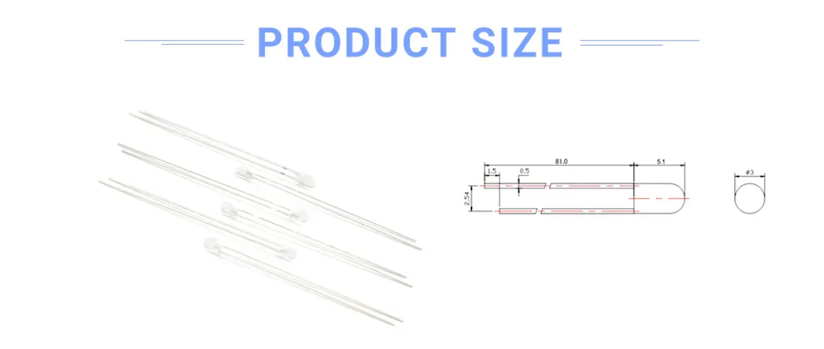
When we see a through-hole LED(DIP LED), there will have two part in a standard through-hole LED: the lens part and the pins part.
For the lens, it will be a white diffused lens, colorful diffused lens, colorfule clear lens or transparent clear lens. And te other part is the pins. Common pins will have the length on 17mm&19mm, 29mm&27mm. In this catalog, we going to show the extra long length of pins with 81mm&79mm or 57mm& 55mm.
Ultra Long Leg LED Lamps, 5mm led long pin, long pin LED, LED Long pin, LED Indicator Shenzhen Best LED Opto-electronic Co.,Ltd / BESTSMD CO LIMITED(HK) , https://www.bestsmd.com
(2) Impedance matching: If the impedances do not match when the microphone is connected to a speaker or other device, the output power of the amplifier will be unevenly distributed, or the transient characteristics of the overdamped ambassador will deteriorate. Impedance matching connections are generally balanced and unbalanced. Balanced means that the two-core shielded line of the transmission signal has the same impedance to ground. The so-called unbalanced type refers to two-core shielded wires, one of which is grounded. When the balanced output is connected to an unbalanced input, matching transformers must be added for matching. The output impedance of a typical pickup is 600 ohms unbalanced.
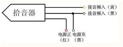
Connection method <br> <br> pickup pickup connector is connected to the recording equipment, hard disk recorders, speakers and computer sound card is to rely on a variety of connectors to complete, there are several commonly used connectors. 

Pickup connection basic requirements and plug-in connection
Basic requirements for the connection of pickups (1) Matching of signal levels: When connecting pickups, it is necessary to pay attention to the differences in input and output signal levels between the devices. If the level of the input signal of the fore-stage equipment is too large, non-linear distortion will be generated. Otherwise, the signal-to-noise ratio of the playback system will be reduced, and even the amplifiers of the next-level equipment will not be able to be pushed. Therefore, attention must be paid when using the equipment. The levels should not differ too much. If the signal level does not adapt in actual use, the input signal level must be reduced by the attenuation circuit, or the level of the input signal must be increased by the amplifier circuit. For pickups, because the output signal level is 0.75~1Vpp or more, they can be sent directly to the “LineIn†port of the audio device.