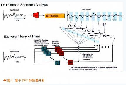
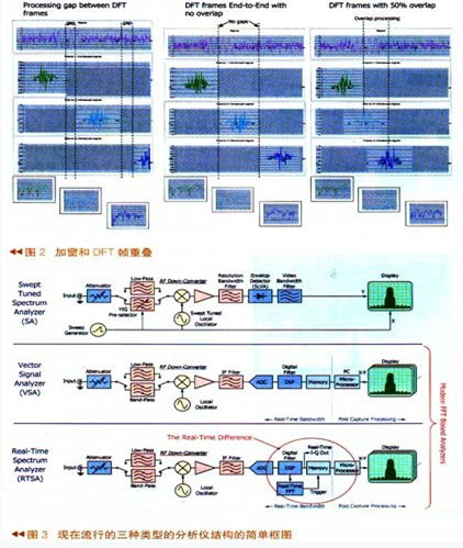
Real-time signal processing definition The term “Real time†was first derived from the digital simulation system of a physical system. If the speed of the simulation system matches the speed of the real-time system it simulates, we consider the digital system to be real-time. To analyze the signal in real time, it means that the execution speed must be fast enough to accurately process all the signal components in the relevant frequency band. If you want to process real-time components, you must first sample the input signal fast enough to satisfy the Nyquist theorem. This means that the sampling frequency must exceed twice the signal bandwidth. Second, all calculations are performed continuously at a fast enough speed and the analysis output can keep up with any changes in the input signal. Spectral analysis, also known as Fourier analysis, analyzes signals from the frequency domain. When using DSP, it means performing discrete Fourier transform (DFT) on time-sampled data. Using the DSP for Fourier analysis is shown in Figure 1. After the input analog signal passes through the A/D and then passes through the DFT engine, the FFT spectrum of the input signal is obtained. It can be seen that there is still some time gap between each FFT sample in this figure. . The entire spectrum analysis process in the above figure is equivalent to the following figure in which the signal first passes through a group of bandpass filters, where the bandwidth and center frequency of each filter are separated by the DFT base unit. For each frequency domain unit, I and Q or amplitude and phase complex envelopes are calculated. If the complex envelope is sampled, when the sampling rate is equal to the speed of the FFT of the signal in the above figure, the two results obtained are Exactly the same. Shown above is a non-real-time FFT spectrum analysis process. For real-time spectrum analysis, there are two criteria that must be met: 1. The input signal must be sampled fast enough to satisfy the Nyquist theorem, and the sampled signal speed is greater than twice the signal bandwidth. 2. The DFT calculation must be performed fast enough that each DFT frequency domain unit meets the Nyquist standard. Windowing and DFT frame overlap The function of the window function in DFT is to reduce the spectral leakage in the FFT spectrum analysis, but sometimes it just blocks the effective information. The leftmost picture is the case where there is a time gap in the DFT processing. The middle picture is the DFT immediately adjacent, there is no time slot, and the frame overlap technique is adopted in the right picture, that is, the second frame data shares the first frame data. As can be seen in the left figure, a short pulse signal appears in the time domain, but since the pulse signal is just between the two DFTs in the time domain, it is directly lost when the transformation is performed. As can be seen from the middle figure, since the appearance of short pulses happens to be at the edge of the adjacent window function, it is also suppressed. That is to say, the signal was sampled, but it was minimized when doing digital processing. In the right picture, the overlapping DFT technique is adopted. Since the first frame and the second frame overlap, the FFT is calculated by overlapping, and the spectrum of the pulse signal of the second frame is easily displayed. Therefore, when performing spectrum analysis, the use of frame overlap technology greatly enhances the signal transient processing capability. From the conventional swept spectrum analyzers of the 1960s to the vector signal analyzers introduced in the 1990s, and today's spectrum analyzers from Tektronix, signal processing technology has gone through three phases. The spectrum tester of the 1960s was mainly used for military and communication systems. The signals tested were mainly analog signals, and most of them were steady-state signals. At that time, the requirements for test instruments were mainly low noise floor and relatively high dynamic range. In the 1990s, complex digital modulation coupled with the rapid development of communication technology, the test signal mainly based on digital modulation signals. Today, with the infinite development of DSP software, the emergence of adaptive modulation signals, transient signals, and frequency hopping and frequency-modulated radar communications has made the testing of transient signals more and more demanding, redundant time-related analysis, Seamless capture, as well as arbitrary position triggering of frequency domain events, are excellent tools for analyzing such transient signals. To better understand how the real-time spectrum analyzer works, we can take a cursory look at the simple block diagram of the three popular types of analyzer structures (Figure 3). Although there are many similarities in the analyzer, such as input attenuators, there are many differences.
Side Glow Fiber is different from solid core side glow fiber. It is a new and green lighting product, of which the diameter ranges from 0.75mm to 3.0mm.
DSPO manufacture a range of fibre optic side glow, which are used widely on all sorts of decoration engineering , such as building , nightclub , disco , hotel , market , plaza and museum , and honored as an honored as an ideal material to replaced current means of decorative illumination.
We make customized different size of side glow fibre optic , you are welcome to let us know your requirements and application . Fibre Optic Side Glow,Side Glow Fibre Optic,Side Glow Optical Fiber,Side Emitting Fibre Optic Jiangxi Daishing POF Co.,Ltd , https://www.opticfibrelights.com
The shortest time we define 100% to capture a non-repetitive event is to capture the duration of the narrowest rectangular pulse. To process all of the signal information of interest in real time, you must first have enough capture bandwidth to support the signal of interest. Second, a sufficiently high ADC clock rate exceeds the Nyquist standard. Third, there is a sufficiently long capture interval support to analyze the narrowest resolution bandwidth (RBW) of the signal of interest. Fourth, a sufficiently high DFT conversion rate exceeds the Nyquist standard of the RBW of the signal of interest. In today's communication systems, there are many narrow pulse communications. To measure and troubleshoot to find problems, it is very important to discover, trigger, and analyze these narrow pulses. 
Used with various light sources such as LED light source, Metal Halide light source, Halogen light source etc., fiber optic lighting has following advantages:
1. Color changing, which is virtually unbreakable and energy efficient;
2. Suitable for interior and exterior applications. It is UV protected, which has an algaecide and fungicide treated exterior jacket for maximum durability against the elements.
3. Side Glow fiber optic cable is strong enough for amusement park rides, extreme cold weather as well as underwater applications. With no heat or electricity in the cable, it is safer compared with typical lighting design restrictions.
Real-time analytics technology and measurement benefits for wireless communications