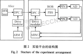
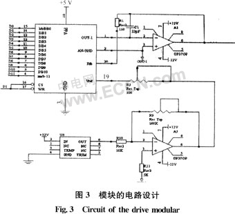
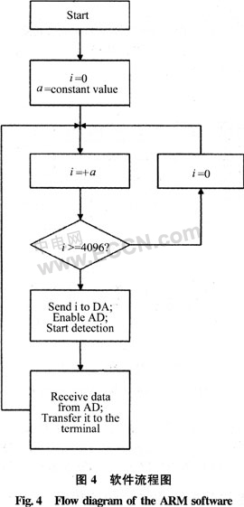
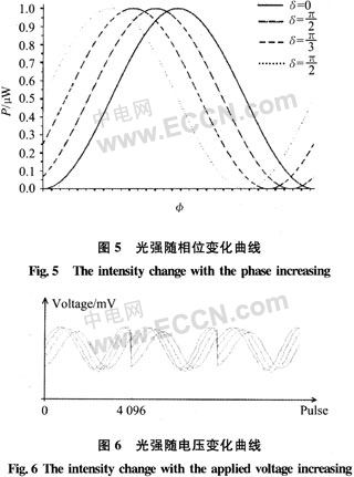
Polarization is an important and commonly used property of quantum light. Therefore, in quantum safety communication systems, codec is often performed by changing the polarization state, and the dynamic polarization controller (DPC), as an optical device that changes the polarization state of the input light, directly participates in the encoding and decoding of the transmitted data, in quantum communication. It plays an essential role. In the traditional optical fiber communication system, how to accurately control the polarization state in the fiber becomes the premise and key of the experiment, because it is related to the stability of the system and the bit error rate of data transmission. It is also very effective to adopt DPC [1, 2]. However, all manufacturers do not give a specific measurement method of the half-wave voltage of their important indicators when they are shipped from the DPC. In practice, the half-wave voltage is not completely consistent with the given nominal value, resulting in inconvenience in use. Therefore, when using DPC, it is necessary to have a matching drive circuit and performance monitoring system. However, if the package is purchased, the price is expensive, and in actual engineering development, the best cost performance cannot be achieved, which hinders the development and promotion of the quantum communication system. Therefore, we need to independently develop and develop the drive circuit and performance monitoring system of DPC. This paper introduces the working principle of DPC, gives the design of its driving module and performance monitoring system, compares the experimental results and theoretical results, and shows the performance of DPC in practical application and many factors affecting its performance. 2 DPC works [3] PolaRITE.II-PCD-002DPC from General Photonics Co., USA, consisting of four fiber extruders, placed at an angle of 45[deg.] to each other. The externally applied pressures corresponding to the optical fiber extruders X1, X2, X3 and X4 are F1, F2, F3 and F4, and the corresponding driving voltages of the respective extruders are V1, V2, V3 and V4 and are driven by voltage signals to generate The corresponding pressure squeezes the fiber to form a linear birefringence that changes the polarization state of the incident light. The polarization state of a single mode magnetic field can be represented by a point on a Bangka ball, as shown in Figure 1. If you increase the voltage V1 or V3 of X1 or X3, that is, increase the pressure F1 or F3 of X1 or X3, the polarization state will rotate clockwise around the OQ axis; on the contrary, if V1 or V3 is decreased, the polarization state will surround the OQ axis. Anticlockwise rotation. On the other hand, if the voltage V2 of X2 is increased, that is, the pressure F2 of X2 is increased, the polarization state will rotate clockwise around the OH axis; conversely, if V2 is lowered, the polarization state will rotate counterclockwise around the OH axis. It can be seen that as long as the polarization state of the input light is not perpendicular to the directions of X1 and X2, the polarization state of the input light can be changed to any one of the polarization states by operating at least two extruders. This extruded fiber type polarization control replaces the traditional half-wave plate, λ/4 wave plate and half-wave plate structure, and thus has: 1) due to the all-fiber structure, DPC insertion loss is low, no reflection; 2) control Fast speed, response time <35μs; 3) Wide working range, working wavelength is 1260~1650 rnm, this feature can simplify system design, reduce cost and make system expandable; 4) Fiber extrusion when working at 1550nm The half-wave voltage of the device is <30 V instead of the half-wave voltage Vπ of the 1550 nm wavelength. Easily converted. 3 DPC driver module design DPC's drive circuit and performance monitoring system was developed and developed through the platform shown in Figure 2. The experimental platform shown in Figure 2 is actually a quantum safety communication system based on coherent optical polarization modulation. Its biggest feature is the use of embedded system ARM controller to realize synchronous driving and monitoring of DPC. The platform uses two DPCs, DPC 1 for modulation and encryption of the coherent optical polarization, and DPC 2 for decryption. Taking DPC2 as an example, DPC 1 does not work when performing performance monitoring of DPC 2. The ARM 2 outputs data that drives the DPC 2 to change the polarization state of the input light. At the same time, the optical signal intensity output by the AD detection is converted into data, which is received by the ARM 2 and transmitted to the computer for processing by the performance monitoring software. According to the working principle of DPC, in order to change the polarization state of the input light to any polarization state, at least two fiber extruders need to be driven at the same time. At the same time, the DPC comes with a 15x voltage amplification module, while the half-wave voltage <30V operates at 1550 nm. Therefore, the maximum voltage required is 30 × 2 / 15 = 4 V, the driver module needs to provide four 0 ~ 4 V variable voltage to drive the DPC's four fiber extruder. As shown in Figure 2, the DPC driver module converts the 12-bit data (0 to 4095) output by the ARM controller to a 0 to 5 V analog voltage through a digital-to-analog device. Its circuit structure is shown in Figure 3. The four voltage-drive designs are identical, all using a high-precision 12-bit DAC (AD7545) with a 5 V unipolar mode of operation. The reference voltage of the AD7545 is provided by the chip REF02, and its voltage floats <5%, which basically meets the accuracy requirements. 4 Performance monitoring system design and results verification The correspondence between the operating voltage and the polarization state applied to the DPC is a very important performance indicator of the DPC, reflecting the performance of the entire communication system. Therefore, when performing performance monitoring on the DPC, it is necessary to monitor the feedback of the intensity signal with the operating voltage in real time. In addition to the hardware of the above experimental platform, the performance monitoring system also needs to write the corresponding software on the ARM controller to realize the driving and monitoring of the DPC synchronization, and feedback the light intensity change back to the computer. The curve of change is shown. 4.1 Software Design Ideas ARM controllers play an important role in the overall performance monitoring system. On the one hand, the data signal (0~4095) is sent to the DPC at a certain interval; on the other hand, the data converted by the AD detection light intensity is received and transmitted to the computer for special software to depict the half wave. Voltage curve. The software flow chart of the ARM controller is shown in Figure 4. 4.2 Theoretical analysis For Fig. 2, if the initial values ​​of the extruder voltages of the DPC 1 are set V1 = V2 = V3 = V4 = 0, it can be used as a device diagram for testing the half-wave voltage of each fiber extruder of the DPC 2. Taking X2 of DPC 2 as an example, a calculation method of half-wave voltage is given. It is known that if the voltage V2 of X2 is increased, the polarization trajectory rotates clockwise around OH, and the voltage change of one rotation is corresponding to twice the half-wave voltage. The Stokes parameter of incident light [4] is Since the DPC is a passive device, the energy is conserved, ideally S0 does not change. Since the trajectory of the polarization state rotates around the axis OH, the parameter S1 does not change. If S1 and S0 are unchanged, it means that the projections EOx and E0y of the incident light wave on the fast axis OX and the slow axis OY in a given polarization state do not change with time. The essence of increasing V2 causing the changes of S2 and S3 is that the phase difference δ1=δy-δx between E0x and E0y changes periodically with V2 [5]. Set the initial phase of the incident light δx=a, δy=a+δ1, the phase difference caused by the X2 voltage changes to φ, and because the fast and slow axis of the fiber and the fast and slow axis of the PBS do not overlap in general, in order to obtain a general situation, It can be assumed that the angle between the two is θ, then the optical modes [6] from the two outlets of the PBS are respectively Because only the change of light intensity at the exit of PBS can be observed, the half-wave voltage of DPC can be determined. Take T1 as the research object and the intensity is 4.3 Experimental verification The half-wave voltage of each fiber extruder of the DPC can be determined using the system shown in FIG. It is possible to set the voltages V1, X3 and V4 of DPC 1 and DPC 2 to be 0, that is, different phases δ1 can be used, and then V2 of DPC 2 can be changed from 0 to 5 V, and DPC can be measured. The half-wave voltage of 2 and X2 is shown in Figure 6. 4.4 Comparison of theoretical and experimental results 1) By comparing Fig. 6 and Fig. 5, the experimental results are basically consistent with the theoretical analysis, that is, the detected light intensity and the applied voltage applied to the DPC obey the sinusoidal variation law. Moreover, in Fig. 6, the relationship between the voltage period T expressed by the number of pulses and the half-wave voltage of the theoretical analysis is Where: C represents the accuracy of the DA conversion; factor 15 represents the multiple of the DPC's own voltage amplifier to amplify it after driving the module's output voltage. Thus, the consistency of the experiment and theory can be verified. 2) Observing Figure 6 shows that the curve has a sudden change. This is because the driver module supplies 0 to 5 V, and the voltage corresponding to one cycle of light intensity is 0 to 4 V. Therefore, after the light intensity changes by more than one cycle and the DA output is 5 V, the abrupt output is 0 V, and the light intensity is also abruptly changed. 3) Figure 6 shows that when the initial phase difference δ1 is different, the peak value of the measurement curve is not exactly the same as the theoretical analysis, and the curve is jittery and not smooth. The main reason is that the elliptical polarization state cannot be well maintained in the fiber. Two cases are assumed: in the first case, DPC 1 plus δ1, DPC 2 plus φ; in the second case, DPC1 plus 0, DPC2 plus δ1 + φ. In theory, the results of these two cases should be the same. However, the actual situation is different, and the difference is that the elliptical polarization state cannot be well maintained in the fiber. 5 Conclusion The drive module and performance monitoring system designed for DPC were studied. The driver module adopts 12-bit high-precision DA chip, which has simple design structure, high conversion precision, stable and reliable. The performance monitoring system utilizes the powerful control of the embedded system, and the communication interface with the computer is simple and fast. It uses the ARM controller to synchronize the drive and monitor, and then writes the application under Windows to display the light intensity under its monitoring. With the curve of the working voltage, the polarization state changes linearly with the operating voltage of the DPC. The results of the experiment are basically consistent with the results of the theoretical analysis, which further indicates the feasibility of the scheme. This method of performance monitoring will be a powerful aid to DPC applications. Rotary Vane Pump,Harbor Freight Vacuum Pump,Liquid Ring Vacuum Pump,Water Vacuum Pump Dongguan Beqile Mechanical&Electrical Equipment CO.,LTD , https://www.betemvacuum.com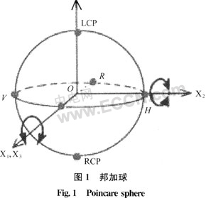
![]()

![]()

![]()
:
Dynamic Polarization Controller Drive and Performance Monitoring System Design
1 Introduction
1 time
Window._bd_share_config = { "common": { "bdSnsKey": {}, "bdText": "", "bdMini": "2", "bdMiniList": false, "bdPic": "", "bdStyle": " 0", "bdSize": "24" }, "share": {}, "image": { "viewList": ["qzone", "tsina", "tqq", "renren", "weixin"], "viewText": "Share to:", "viewSize": "16" }, "selectShare": { "bdContainerClass": null, "bdSelectMiniList": ["qzone", "tsina", "tqq", "renren" , "weixin"] } }; with (document) 0[(getElementsByTagName('head')[0] || body).appendChild(createElement('script')).src = 'http://bdimg.share. Baidu.com/static/api/js/share.js?v=89860593.js?cdnversion=' + ~(-new Date() / 36e5)];