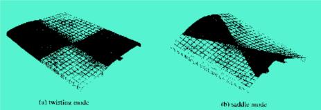
4.4 Welding deformation prediction of large structures Figure 8 Welding deformation of large cylinder structure 4.4.2 Welding deformation of large hull structure Figure 9 hull structure welding deformation 4.4.3 Welding deformation of extra large floating structure Figure 10 Assembly of the floating structure Figure 11 Deformation of the floating structure 4.5 Welding stress and deformation of aluminum alloy structure Figure 12 Aluminum alloy π-section structure The analysis was carried out using the inherent strain finite element method of the shell element. Figure 12 is an aluminum alloy π-section plate in the structure of the car. Figures 13 and 14 show two different forms (twisted and saddle) of the predicted weld instability deformation, respectively. They are related to the π-section shape size. From an energy point of view, the torsion type is preferable to the saddle type. Figure 13 Torsional deformation Figure 14 Saddle deformation Previous Next
The high chromium wear-resistant alloy steel balls produced by our company have the following advantages:
1. With extremely high hardness, usually between 60-66 HRC, it can effectively resist wear and grinding and extend service life.
2. Excellent wear resistance, able to maintain stable performance during high-speed grinding and grinding, reducing the risk of wear and fracture.
3. It has good impact resistance and can withstand greater impact force and is not easy to break during high-speed grinding and grinding.
4. It has good corrosion resistance, can maintain stable performance in wet and corrosive environment, and is not easy to rust and corrosion.
5. Can maintain stable performance in high temperature environment, not easy to deform and soften, suitable for high temperature grinding and grinding process.
6. The wear rate of the steel ball is low, which can reduce the loss of abrasives and materials and improve the grinding and grinding efficiency.
Chromium Oxide Abrasive,Alloy Steel Ball,Tempered Alloy Steel Balls,Wear Parts Steel Ball Xuzhou Surun wear-resistant material Co., LTD , https://www.suruntools.com
4.4.1 Prediction of welding deformation of large hull structure
Two ribbed hulls with a diameter of 1700 mm were docked with multiple welds. The three-dimensional residual plastic deformation finite element analysis method was used to compare the welding deformation of ribbed and ribless hulls. Figure 8 shows their residual deformation after welding. After multiple passes, the diameters of the intermediate sections of the ribbed and ribless hulls are shortened by approximately 1.0 mm and 1.2 mm, respectively. The axial shrinkage of the two types of cylinders is almost the same about 1.5 mm. The above calculations are similar to the relevant simulation test data. Using this method, the effects of different welding heat input, bearing and supporting conditions on welding deformation were also studied, which provided reference and basis for actual production. 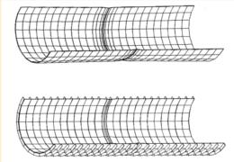
Figure 9 is a prediction of the welding deformation of a large-sized hull structure using the inherent strain finite element method of the shell element. 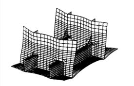
The Mega-Float is assembled from many large units one by one. At this time, the welding sequence and gap control have a great influence on the dimensional accuracy of the structure. Figures 10 and 11 show the assembly sequence of the floating structure and its effect on the deformation. 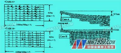
4.5.1 Analysis of welding residual stress of aluminum alloy I-beam
The thermal elastic-plastic finite element method is used to analyze the welding residual stress of aluminum alloy I-beams with different joint forms to select the best joint form and to exert the maximum bearing capacity of aluminum alloy welded I-beam. The theoretical prediction of the welding residual stress is in good agreement with the cutting method.
4.5.2 Analysis of welding instability deformation of π-section plate of aluminum alloy 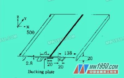
Virtual Engineering and Welding Mechanics Numerical Simulation (4)