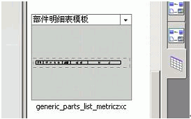
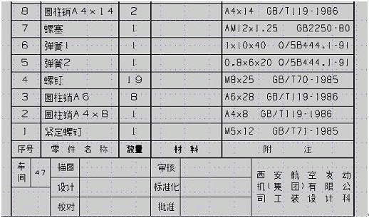
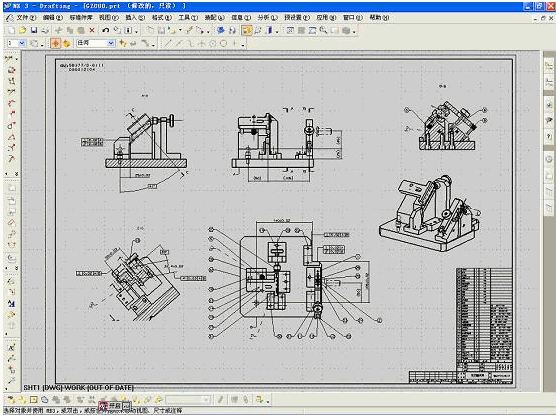
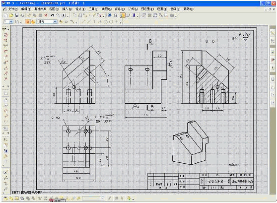
Pagination Save the drawing template file consisting of the frame and the title bar to the UGSNX 3.0UGIIhtml_files subdirectory of the UG installation directory, edit and edit the file metric_drawing_templates.pax in the subdirectory, and add the designed frame template. Add the following content: In this way, the drawing template icon shown in Figure 5 will appear in the resource bar on the right side of the screen. Click this icon to display various drawing template types. Figure 5 When the designer uses it, click on the selected web button to generate a set drawing template. Adding various views to the template map, and dimensioning and technical requirements (marking styles have been set), you can complete the drawing of zero and part drawing. 2.3 Automatic generation of schedules Design the following schedule format in UG's Drafting environment, and use the "relationship" command in the annotation editor of UG to associate columns of names, materials, and notes with part attributes, and set attributes such as font and word height. As shown in Figure 6. Image 6 Save the resulting file to the UGSNX 3.0UGII able_files subdirectory of the UG installation directory, edit the file table.pax in the subdirectory, and add the designed schedule. In this way, the table icon shown in Figure 7 will appear in the resource bar on the right side of the screen. Click this icon to display various table types. Drag the selected schedule header to the drawing area to automatically generate a schedule of the model. As shown in Figure 8. Figure 7 Figure 8 Pagination Figure 9 shows the assembly drawing of the fixtures using the self-made template design. Figure 9 Figure 10 is a part drawing of a fixture using a self-made template design. Figure 10 3. Conclusion The establishment of UG drawing template provides the possibility for UG software to be applied to the production practice of tooling design. Designers can use UG 2D engineering drawing template to directly use UG software to produce engineering drawings, so that UG engineering drawings and UG 3D models are related to each other. Thus, when the tooling 3D model is modified, the projections and dimensions in the engineering drawings are changed. In order to avoid the unnecessary waste and the possibility of error caused by human modification, improve the quality and efficiency of the three-dimensional design. At present, some of our designers have adopted UG software for tooling design, and directly out the engineering drawings. After two or three months of use, the effect is remarkable. Previous page Dressing Table,Vanity Table,Makeup Table,Dressing Table Furniture PFALL , https://www.pfallfurniture.com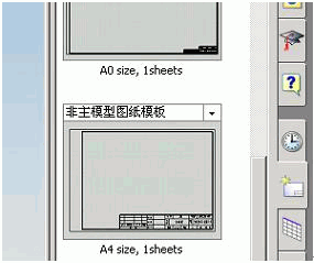

Application of UG Drafting in Aerofonic Tooling Design (2)