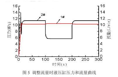
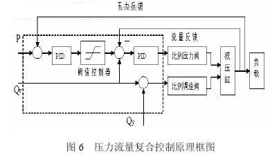
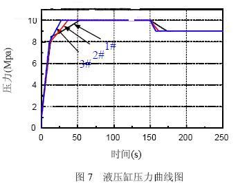
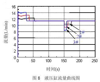
3.1.2 Propulsion flow open loop control simulation The flow rate of the flow valve is set to 11.4L/min, the pressure valve is 10.5Mpa, and the load speed increases from 0 to 0.001m/s when the pressure reaches the set value of 8.5Mpa. The flow valve is adjusted to 11.4 L/min at 100 s and to 5.7 L/min at 200 s. The load speed is adjusted to 0.0005 m/s at 100 s and 0.001 m/s at 200 s. Figure 5 is a graph of hydraulic cylinder pressure and flow when adjusting flow. The 1# curve is the hydraulic cylinder pressure change curve, and the 2# curve is the hydraulic cylinder flow rate change curve. It can be seen from the simulation results in Fig. 4 and Fig. 5 that the simple pressure control will cause the flow fluctuation, and the simple flow control will cause the pressure fluctuation, and neither of them can achieve a good control effect. 3.2 Pressure flow composite closed-loop control mode In order to achieve pressure-flow composite closed-loop control, the following control principles are employed. The pressure flow signal of the hydraulic cylinder is separately collected and fed back. The proportional pressure valve is used as the main actuator of the pressure flow combined control. The proportional flow valve realizes the control of the flow range, providing the necessary pressure for the normal propulsion of the hydraulic cylinder and the stable overflow of the proportional pressure valve. Traffic, as shown in Figure 6. The propulsion load speed is ramp input, which is 60mm/min from 0mm/min within 30s, the flow valve flow rate is set to QV+QY=20l/min, the pressure valve P is 10Mpa, and the pressure valve is adjusted to 9.0Mpa at 150s. The adjustment of the enthalpy value of 1, 2, 3 respectively can be obtained as shown in Figure 7, and the flow curve is shown in Figure 8. Increasing the threshold increases the pressure loop control time, but increases the system flow fluctuation accordingly. Decreasing the threshold can significantly reduce system flow fluctuations, but increases the control time of the system pressure. However, compared with pure pressure or flow control, the pressure and flow fluctuations have been greatly improved, and the control effect has been significantly improved. 4 Conclusion The simulation results show that the conventional pressure control under the shield propulsion condition will cause the flow to fluctuate drastically, and the conventional flow control will cause the system pressure to fluctuate. The pressure flow combined control mode can perform both pressure closed loop control and flow closed loop control. At the same time, by adjusting the threshold value, the speed fluctuation of the hydraulic cylinder caused by the pressure regulation can be reduced to some extent. Previous page Backyard Swim Spa,Public Hot Tub,Whirlpool Swimming Pool,Portable Big Swim Spa Pool SpaRelax Co., Ltd. , https://www.sparelaxoutdoorspa.com
When the flow rate is increased, the hydraulic cylinder speed rises and fluctuates, and the pressure changes slightly. When the flow rate is lowered, the hydraulic cylinder speed fluctuates and the pressure has changed slightly. The small change in cylinder pressure depends on the change in the overflow of the proportional relief valve. 
The composite control adopts closed loop control of inner loop flow and closed loop control of outer loop pressure. In order to reduce the maximum fluctuation of flow rate, a threshold controller is added after pressure closed loop PID control, and the maximum change of flow rate can be controlled by setting the threshold value. P is the system control required pressure, QV is the flow required for the normal propulsion of the hydraulic cylinder, and QY is the flow required for the proportional overflow valve to stabilize the overflow. 

Simulation Analysis of Shield Machine Propulsion Hydraulic System (2)